These are just some things I've learned in the past few weeks of ownership and I thought I'd pass them along.
Instead of using C7/E12 incandescent bulbs, in the door I used
these. They are BRIGHT. I went with the soft white to match the color of the lighted panel fluorescent. They have a daylight(a bit of bluish tint) as well that I tried. I used some lower watt LEDs for the Use Correct Change and Have a Coke lights. I just picked those up at Home Depot. One thing you may see is even when off the LEDs glow a bit. If this happens and you've got a 2 prong AC plug, try switching around if possible.
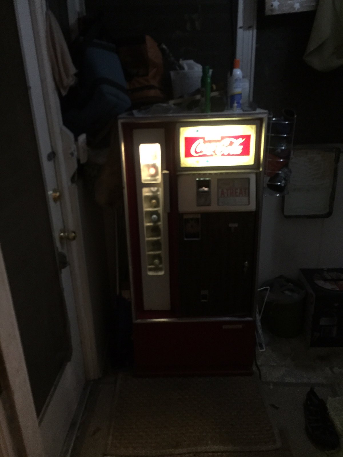
Blurry picture of the soft white LED:

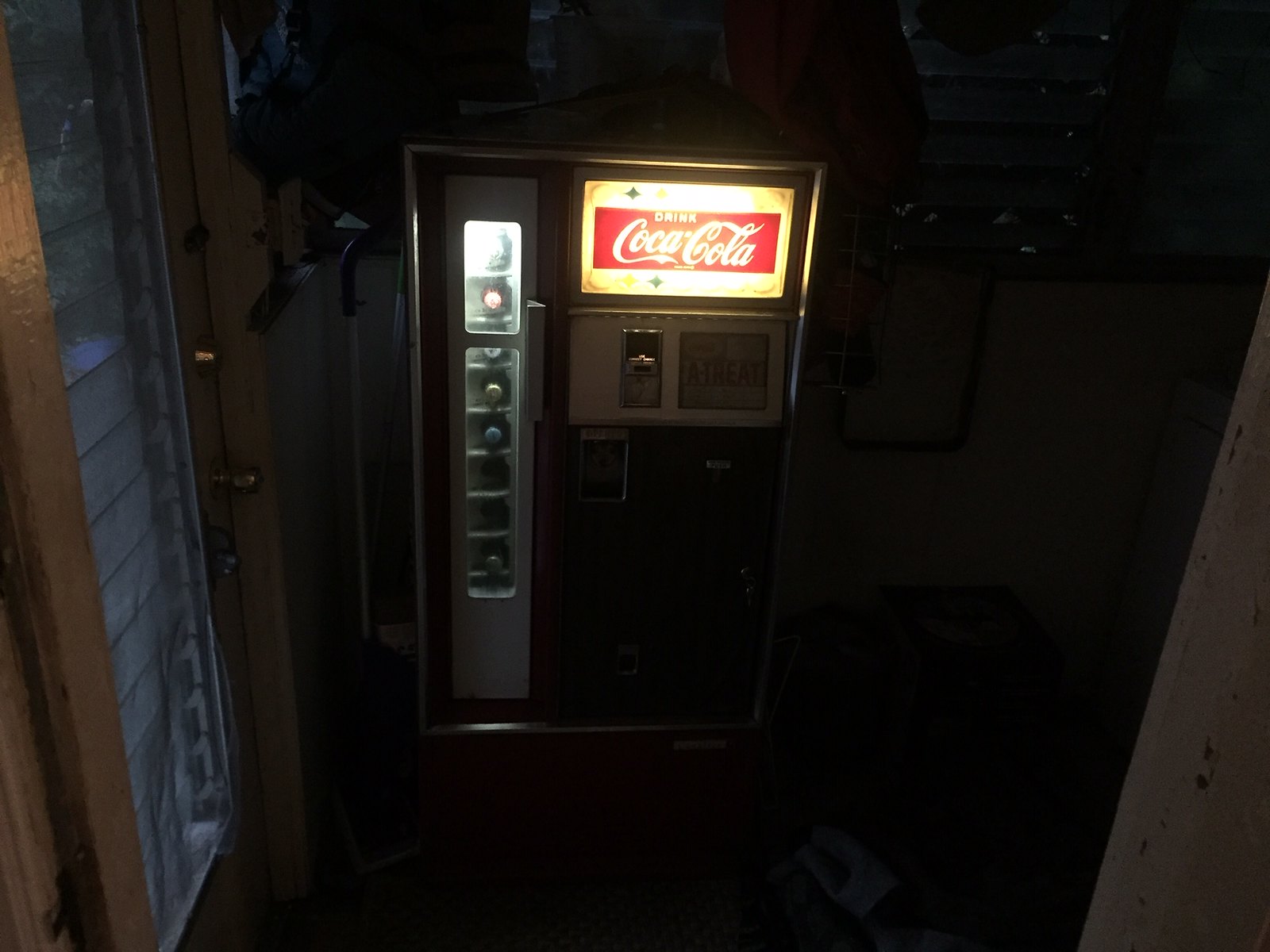
Blurry picture of the daylight LED:

For those with a Coin Acceptors fp 9800 807 a couple of things to do.
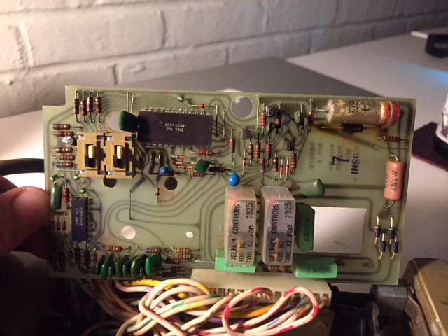
1) Replace the 220UF capacitor on the logic board. The Coinco manual:
here on page 6 Figure 3-5 shows the capacitor. Electrolytic caps dry out over time if they are pass voltage. Mine looked ok, I was expecting to see bulges at either end, but internally it had failed. When I pulled it out of the board to measure, the value was way off. So rule of thumb, just replace it. I didn't have a 220UF but close enough with a 250UF. More capacitance is ok, what you need to make sure of is the voltage rating of your replacement cap is at least 25V DC, more is fine, less will get you a firecracker.
The capacitor is the piece at the top right corner of this pic:
 logic_board_2
2) The changer motor assembly is a pretty robust 1 phase electric motor. This is where the Coin Acceptors I have differs from the Coinco(at least based on what I see in the manual listed above.
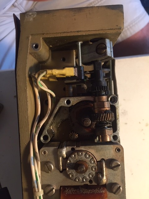
This is a picture of mine with the top of the motor case removed:
 motor_assembly
The round piece at bottom of the picture is the rotor, it's what spins and then goes through the reduction gearing you see above it. I thought the output shaft was binding(that's the gear you see on the right side middle of the picture). It's what is connected to an arm that moves the changer back and for to dispense the nickles. There is a momentary switch that a cam lobe touches to tell the logic board each time a nickle is dispensed.
My issue turned out to be the rotor wasn't spinning when the windings are energized. Basically the rotor sits in the middle of an electro magnet, when it's energized, it causes the rotor to spin. I never found any physical reason why it wasn't spinning, I think me taking it apart and putting it back together about 1000 times finally made it happy. I light sanded the rotor and put some De Oxit(tuner cleaner) on it.
While you have the motor apart, clean the grease out of there. Mine was so set up at first I thought it was a broken part. Turned out just to be some hardened grease. I pulled the gears out and wiped them down and used some spray on white lithium grease. My machine is not going to be pulling heavy work loads anymore, so I didn't repack it with a heavier grease.
The motor concerns me because when it gets hung, it will get very hot. Best to test the mechanism from time to time with the inventory switch. In theory mine should never run since I've set it to $0.25 and all I use is quarters, however it does decide sometimes it's got to make change.

